
Smore logo
remove_red_eye 81
page background

LR Lab

LR Lab

Circuit Construction Kit: AC

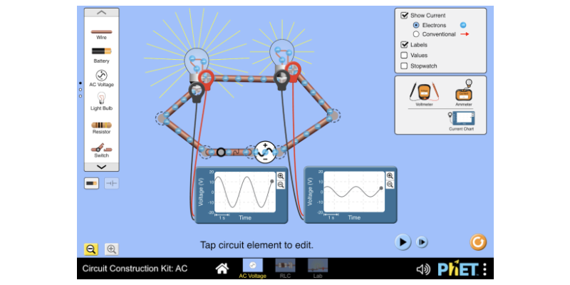
Experiment with an electronics kit! Build circuits with batteries, resistors, ideal and non-Ohmic light bulbs, fuses, and switches. Build circuits with AC voltage sources, batteries, resistors, capacitors, inductors, fuses, and switches. Take measurements with a lifelike ammeter and voltmeter and graph the current and voltage as a function of time. View the circuit as a schematic diagram or switch to a lifelike view.

launch phet.colorado.edu

Launch the Circuit Construction Kit simulation - Select RLC Launch the Circuit Construction Kit simulation - Select RLC

Purpose

Examine the behavior of LR circuits.

Materials

internet and computer

PreLab

  1. What is the unit of the quotient of inductance and resistance? Show your work below.

  2. The quotient of L and R is called the time constant. The Greek letter tau is used to represent the time constant.
  3. An inductor will be fully charged/discharged in a time of 4 to 5 time constants.
User uploaded image
zoom_out_map

Procedure

  1. Open the simulation and select RLC.

  2. Construct the circuit to the right.

  3. Set values to:
    Battery voltage = 10 volts
    L = 10 henries

    R = 10 ohms

  4. Calculate the time constant.

  5. Add the necessary meters and sketch the graphs of i vs t, and V vs t, for the resistor and inductor when the inductor is charging and discharging.

READ CAREFULLY READ CAREFULLY

NOTE - It is not possible to flip the switches fast enough for LR effects to be observed - try and see.


Here's what has to be done.


RISE of CURRENT

1. Open both switches.

2. Close the top switch.


DECAY of CURRENT

1. Once the inductor has been fully energized, click the PAUSE button.

2. Adjust the switches. Bottom switch to close, Top switch to open.

3. Unpause the simulation.

User uploaded image
zoom_out_map Show in original size

Questions

  1. When is the brightness of the bulb increasing?

  2. When is the brightness of the bulb decreasing?

  3. When does the battery supply the potential to light the bulb?

  4. When does the inductor supply the potential to light the bulb?

  5. Does the direction of charge flow change through the inductor? If yes, explain when.

  6. Complete the chart below
User uploaded image
zoom_out_map Show in original size
David Carroll - Plano West
www.GravityKills.net
Loading indicator

close

Created with

Communicate quickly and effectively with interactive newsletters.

Smore empowers educators to connect with their community, streamline school communications,
and increase engagement.

Create a newsletter